

Wednesday, November 25, 2015
Saturday, November 21, 2015
Adding to the Stable...
I had an outstanding year thus far in the saddle of my 2015 Kawasaki Versys 1000 LT. Two major trips out west where we scaled all 14,000 feet of Pikes Peek, visited the Grand Canyon and knocked a loop around the Apache Trail in Arizona. Then I had a bunch of shorter, regional trips including a myriad of rides around Florida, including a great Key West/Everglades trip, and then a couple runs up to the Smoky Mountains in North Carolina. All in all, 18,500 miles worth of road trip.


Unfortunately, now I'm stuck in Florida until at least late May (2016). That's great from the standpoint that I have year 'round riding capability. It's not so great from the standpoint that there's not too much in terms of good riding here in Flatistan. Unimaginative, long straight roads, no elevation to speak of, been to about everywhere, done about everything.
One area of riding that I got to thinking may compensate for this shortfall is dual sport. I have a long history of dirt and adventure riding, dating back to the mid-70s, but broke away from it back around 2012 following an adventure ride up to Deadhorse, Alaska. Plus, there are a number of dual sport clubs that I continue to belong to since those days; Dixie Dual Sport, for example. I know these clubs are constantly sponsoring rides. So yeah, I decided to jump back in.
As for the equipment, I landed on a motorcycle that has been around (in basically the same form) since the mid 80s ... the 2016 Kawasaki KLR650.

Specs for the KLR650 are...

Somewhat antiquated in its engineering (carburation, mediocre suspension), the KLR650 is probably going to need quite a bit of modification. However, that's one of the characteristics that attracts me too this model. I mean, at $6,900 (msrp) there's quite a bit left in my wallet to work on fine tuning this booger to my liking and, as you can tell by now, I like wrenching on my bikes.
Plus, the new digital camo is extremely kewl looking!


So, where and when do I get one of these bad boyz? I set my dealer on a course of finding me one as soon as possible. The sales manager got back to me and confirmed my order and delivery in two to three weeks. That's around first week in December. Enough time to have a great time in the Ocala National Forest, Richloam, Withlacoochee State Forest, Everglades National, etc. etc. etc. this winter and spring.


So, not to get my Versys Ventures Blog all congested with non-Versys stuff, I've started a new blog called KamoKLR on Blogspot to chronicle the KLR650 travels and mods.
Tuesday, November 10, 2015

Monday, November 9, 2015
Wheel Alignment
When my dealer changed my tires back in July, they left about four inches of slack on the chain; way too much. The spec is 1.0 -- 1.4 inches. I could hear it slapping all the way home. So when I got home, I pulled out my 27 mm socket, loosened the axle nut and took the excess slack out.
Realignment of the rear tire follows the typical method of aligning the slides (both sides) against the notches on the swing arm. Seems fairly simple, but it seemed like every time I looked at it one side or the other didn't appear properly lined up with the other.
The problem is two-fold. The first, and biggest problem, is my visual acuity isn't anywhere close to where it used to be. Even with reading glasses, it's hard to focus in on real small things. The second, is that the alignment notch on the slide block is recessed in the swingarm while the row of alignment notches on the swingarm are on the outer edge. So the lines don't come exactly together anyplace and it's like a 10 mm spread. It makes for somewhat of an optical illusion trying to align the slide notch to the right place inside the sidearm notches that are about 4 mm apart in and of themselves.

I put up with worrying about it long enough and, in connection with some major services I have going on, I decided to get it right on. Very simply, I located a rigid plastic drawer divider that I held to the back, flat surface of the swingarm. Any thin, thin rigid material will do.

Then I measured the front of the slide to the plastic piece with my caliper. Repeat on the other side. What did I find?

The measurement was exactly 66 mm on each side. Exactly! Hey, maybe my old eyes aren't so bad after all. :)
Two good things come out of this. First, I won't be worrying if my tires is out of alignment because I can't see well and, second, I have a new method to measure alignment going forward. Sweet!
Thursday, November 5, 2015
Kawasaki 1000 Valve Clearances
A normal, periodic maintenance procedure for four-stroke motorcycles is the inspection of valve clearances. Very simply, valve clearances are the small gaps between the valve tappet (also called bucket) and the cam lobe. The spinning cams that can contain up to four lobes per cylinder control the air/fuel mixture (intake cam) and the exhaust gases in the cylinder head (exhaust cam). Under the the punishment of high reving motorcycle engines, valve clearances have a tendency to reduce/tighten as the valves, tappets and shims wear. Tolerances are usually established by manufacturers in tenths of millimeters and require feeler gauges to measure. An out of spec clearance can result in everything from poor engine performance (including mileage) to a damaged valve and engine failure.

The 2015 Kawasaki Versys 1000 LT has an inline 4 cylinder, 1043 cc engine, where each cylinder has two intake valves and two exhaust valves. Accordingly, there are 4 valves per cylinder and 16 total valve clearances that require measurement.
The first valve clearance service interval for U.S. and Canadian models is 15,200 miles. Due to an extended trip out west, I had racked up 18,500 miles before getting to my valve clearance measurements. That's not to say that was okay. Rather, it's my understanding that the first valve clearance measurement is the most important. I just got carried away on a road trip.

I'll start with my results and then I'll go through an overview of the process with photos to get the results.
First off are the tolerances established by the manufacturer as provided in the Service Manual:
Since there are a lot of numbers involved, I prepared the template shown below on Microsoft Excel to keep track. From past experience doing this, I've learned that it's important to have a feeler gauge set with a good range of blade sizes for better precision. When using feeler gauges, you're not actually measuring the clearance; you're just sliding a piece of metal under the cam lobe. The more of those blades you have in your set that are inside the tolerance ranges (above), the more precise the measurement. My set is a Sears Craftsman 26 blade, angled feeler gauge. Of that set, a total of 9 blades were within the tolerance range.
Even with a good blade range, my approach for calculating clearance is averaging (Average) the largest blade that I could fit under the lobe (Fit) and the next size up (No Fit). There are other methods. My dealer thought this approach was okay.

Other details on my template ^ are the shim replacement sizes (determined by a table in the Service Manual) and the manufacturer's part number for shims. Please note that the 2.95 mm shim size is the the original shim presumably installed at the factory. When making shim replacement decisions the shims need to be removed and measured using a micrometer because they do wear and you really need to be sure.
For the record, I am not re-shimming the two out-of-spec valves (red measurements) because they're only a matter of a couple hundredths of a mm out of the tolerances. However, I made that decision only after talking to my dealer's service department. Consider the information in the table following the clearance measurements for illustrative purposes only.
Overall, the process involved to check the valves took between six and seven hours, excluding reassembly. I'm still waiting on the replacement valve cover gasket, jeesh!
Aside from a feeler gauge set with a good range of blades, there were no special tools needed.
There are a number of original equipment replacement parts called for as follows:
Also, there will not be a better time to replace the spark plugs (NGK CR9EIA-9), air filter element (No. 11013-0712) and the coolant than during this exercise to get to the valves for tolerance measurement. I'm definitely taking advantage of the opportunity.
Of course, I have a Service Manual and referred to it to do these procedures. There's a lot in there about this process that ain't in this post. In addition, I found the exploded parts diagrams on the Kawasaki Website to be very helpful. After all, pictures are worth a thousand words. The diagrams I found most helpful were the Cylinder Head Cover, Camshaft(s)/Tensioner, Cylinder Head and Valve(s).

...and a good clean work space. A high pressure air hose on a compressor came in handy to blow out the engine compartment.

The first steps involve removal of all the fairings ... and this bike has a lot of fairings! Fairing removal includes both the nose cone and the side panels. Fairing removal is covered in the Service Manual, Chapter 15-9, and I won't go over what I did in detail. It's about a 2 hour exercise. However, there is an outstanding post on the Versys 1000 Forum that I follow and has step by step fairing removal and lots of pictures. Click the link below:
Tech Tip: How to Remove Fairings on 2015 V1K, by Gharsaman.
With all the fairings removed, I then did the following:

Okay, here's where I was at when I got all those procedures done. Caped off the throttle bodies so no contamination get in there and then disconnected and removed the stick coils.

I numbered the stick coils although I'm not sure that replacement to the same cylinder is necessary. Better to be safe than sorry, though.

The next step was to remove the Air Switching Valve (Service Manual, Engine Top End 5-13, 14) and the Air Suction Valve Covers. Note that there's an electrical connector shown in the photo that was disconnected.

With the Air Switching Valve Removed, I could push the rubber cover over the top of the engine into the front area in front of the cylinder head and out of the way. Then the two Air Suction Valve Covers could be removed.


The Service Manual then calls for the Air Suction Valves to be removed. However, I couldn't get them out. They're actually reed valves and I just didn't want to put too much pressure on them and end up breaking or bending them. So I left them installed and there was no interference when I ultimately got to pulling the valve cover.

At this point, the valve cover can be unbolted and removed. There are a couple methods that I considered in getting the cover out of the frame. However, both approaches result in the valve cover being slid out on the right side of the frame.
The first method, which is the Service Manual approach, is to remove the radiator cap housing bolt, which in turn loosens the radiator housing and hoses. Then the housing/hoses can be pulled up and out of the way while the valve cover is slid underneath.

Alternatively, I unhooked the front radiator hose, unscrewed the housing bolt and then lifted the whole assembly out of the way. Not only did this make the valve cover removal easier, it also offer up some more room for working on the valves when I got to that point. See how much more room you have below compared to the photo above?

However, to go my route, the coolant needed to be drained and replaced. It's quite an easy procedure, although I made it a little messy.


Now it was clear sailing to remove the six valve cover bolts and slide the valve cover out the right side of the frame. As it relates to the six bolts, it should be noted that there is a special order for reinstalling them when I get to that. That order is provided on the both the valve cover and in the Service Manual (Cylinder Head Cover 15-18).


Finally, I can see the Cams!


There are four retainer pins that hold the four spark plug gaskets in place. These are loose and could be removed so as not to interfere when testing clearances.

The next step that precedes clearance measurement was placing the pistons in the proper position, which is Top Dead Center or TDC. This was done by turning the crankshaft gear located under the Crankshaft Sensor Cover. The photo below is the Crankshaft Sensor Cover. There are some brackets in this photo that are associated with my aftermarket Power Bronze Belly Pan.

The crankshaft gear (shown below) reflects markings for TDC of pistons #1, #4 and #2, #3. This gets a little confusing, but following the Service Manual, I only used the TDC mark for pistons #1, #4 at the completion of the compression stroke to check clearances.

In its position of TDC 1.4 in the photo above ^, the piston is at the completion of the compression stroke and valves for either piston #1 or piston #4 are closed. The other of those two pistons was placed at TDC wherein its valves are all closed by turning the crankshaft gear 360 degrees using a 17 mm socket and ratchet as shown below. So, the way this works is every full turn of the crankshaft gear alternates Piston #1 and Piston #4 as being at TDC at the end of the compression stroke.

Once the pistons are properly positioned, the table below (derived from the Service Manual) outlined the specific valves that are closed (including valves associated with pistons 2 and 3) and for which clearances could be measured. It provides that when piston #1 is at post-compression TDC, I was free to measure clearances on the exhaust valves of cylinders 1 and 2 and the intake valves of cylinders 1 and 3. Then I would rotate the camshaft gear 360 degrees placing piston #4 at post-compression TDC, at which time I was free to measure clearances on the exhaust valves of cylinders 3 and 4 and the intake valves on cylinders 2 and 4.

The next table (also derived from the Service Manual) shows the lobe position and the proper method for insertion of the feeler blade.

So, as an example, below is a clear view from the left side of the engine of an exhaust lobe (left) and an intake lobe (right) with piston #4 at TDC, which could be established from the lobe position table just above.

Now, I went back to the second table up and note that these two lobes (that are associated with cylinder 1) need to be tested with piston #1 at TDC. That was accomplished with one full turn of the crankshaft gear.

At this point, it was just a matter of using the feeler gauges to measure the clearances and writing them down as I went along. I was very careful not to leave a feeler gauge in the cam lobe! I've heard of that happening.

One thing that I considered, if I got a bad reading, I'd rotate the camshaft gear two full turns to get the piston I'm testing out of and then back to TDC and test it again. Under my overall approach, if ultimately, after discussion with my dealer, a valve or valves is determined to be out of tolerance, the procedure would be to replace the shim (shim under bucket) as shown in photo below.

Since I am not planning on making shim replacements, this is a topic not addressed in this post. However, given how tight the current exhaust tolerances are on my Versys 1000, I am taking the recommendation of my dealer to move up the clearance measurements to 10,000 miles (or 28,500). At that point I may be replacing shims. That'll be a lot more work than is reflected in this post, but that's okay. It just means that I'm keeping my motorcycle well maintained.

The 2015 Kawasaki Versys 1000 LT has an inline 4 cylinder, 1043 cc engine, where each cylinder has two intake valves and two exhaust valves. Accordingly, there are 4 valves per cylinder and 16 total valve clearances that require measurement.
The first valve clearance service interval for U.S. and Canadian models is 15,200 miles. Due to an extended trip out west, I had racked up 18,500 miles before getting to my valve clearance measurements. That's not to say that was okay. Rather, it's my understanding that the first valve clearance measurement is the most important. I just got carried away on a road trip.

I'll start with my results and then I'll go through an overview of the process with photos to get the results.
First off are the tolerances established by the manufacturer as provided in the Service Manual:
- Exhaust = 0.22 mm - 0.31 mm
- Intake = 0.15 mm - 0.24 mm
Since there are a lot of numbers involved, I prepared the template shown below on Microsoft Excel to keep track. From past experience doing this, I've learned that it's important to have a feeler gauge set with a good range of blade sizes for better precision. When using feeler gauges, you're not actually measuring the clearance; you're just sliding a piece of metal under the cam lobe. The more of those blades you have in your set that are inside the tolerance ranges (above), the more precise the measurement. My set is a Sears Craftsman 26 blade, angled feeler gauge. Of that set, a total of 9 blades were within the tolerance range.
Even with a good blade range, my approach for calculating clearance is averaging (Average) the largest blade that I could fit under the lobe (Fit) and the next size up (No Fit). There are other methods. My dealer thought this approach was okay.

Other details on my template ^ are the shim replacement sizes (determined by a table in the Service Manual) and the manufacturer's part number for shims. Please note that the 2.95 mm shim size is the the original shim presumably installed at the factory. When making shim replacement decisions the shims need to be removed and measured using a micrometer because they do wear and you really need to be sure.
For the record, I am not re-shimming the two out-of-spec valves (red measurements) because they're only a matter of a couple hundredths of a mm out of the tolerances. However, I made that decision only after talking to my dealer's service department. Consider the information in the table following the clearance measurements for illustrative purposes only.
Overall, the process involved to check the valves took between six and seven hours, excluding reassembly. I'm still waiting on the replacement valve cover gasket, jeesh!
Aside from a feeler gauge set with a good range of blades, there were no special tools needed.
There are a number of original equipment replacement parts called for as follows:
- Valve Cover Gasket (No. 11061-0914)
- Spark Plug Gaskets (No. 11061-0104)
- Valve Cover Bolt Grommets (No. 92055-0785)
- Camshaft Senor Cover Gasket (No. 92055-0199)
Also, there will not be a better time to replace the spark plugs (NGK CR9EIA-9), air filter element (No. 11013-0712) and the coolant than during this exercise to get to the valves for tolerance measurement. I'm definitely taking advantage of the opportunity.
Of course, I have a Service Manual and referred to it to do these procedures. There's a lot in there about this process that ain't in this post. In addition, I found the exploded parts diagrams on the Kawasaki Website to be very helpful. After all, pictures are worth a thousand words. The diagrams I found most helpful were the Cylinder Head Cover, Camshaft(s)/Tensioner, Cylinder Head and Valve(s).

...and a good clean work space. A high pressure air hose on a compressor came in handy to blow out the engine compartment.

The first steps involve removal of all the fairings ... and this bike has a lot of fairings! Fairing removal includes both the nose cone and the side panels. Fairing removal is covered in the Service Manual, Chapter 15-9, and I won't go over what I did in detail. It's about a 2 hour exercise. However, there is an outstanding post on the Versys 1000 Forum that I follow and has step by step fairing removal and lots of pictures. Click the link below:
Tech Tip: How to Remove Fairings on 2015 V1K, by Gharsaman.
With all the fairings removed, I then did the following:
- Loosen handle bar and turn up for more clearance to the engine compartment.
- Disconnect the negative lead on the battery.
- Perform the procedures to lift the fuel tank up on its pivot (the Service Manual calls for removal of the fuel tank).
- Remove the Air Box.
- Remove the Stick Coils.
- Cushion and cover to avoid damage.

Okay, here's where I was at when I got all those procedures done. Caped off the throttle bodies so no contamination get in there and then disconnected and removed the stick coils.

I numbered the stick coils although I'm not sure that replacement to the same cylinder is necessary. Better to be safe than sorry, though.

The next step was to remove the Air Switching Valve (Service Manual, Engine Top End 5-13, 14) and the Air Suction Valve Covers. Note that there's an electrical connector shown in the photo that was disconnected.

With the Air Switching Valve Removed, I could push the rubber cover over the top of the engine into the front area in front of the cylinder head and out of the way. Then the two Air Suction Valve Covers could be removed.


The Service Manual then calls for the Air Suction Valves to be removed. However, I couldn't get them out. They're actually reed valves and I just didn't want to put too much pressure on them and end up breaking or bending them. So I left them installed and there was no interference when I ultimately got to pulling the valve cover.

At this point, the valve cover can be unbolted and removed. There are a couple methods that I considered in getting the cover out of the frame. However, both approaches result in the valve cover being slid out on the right side of the frame.
The first method, which is the Service Manual approach, is to remove the radiator cap housing bolt, which in turn loosens the radiator housing and hoses. Then the housing/hoses can be pulled up and out of the way while the valve cover is slid underneath.

Alternatively, I unhooked the front radiator hose, unscrewed the housing bolt and then lifted the whole assembly out of the way. Not only did this make the valve cover removal easier, it also offer up some more room for working on the valves when I got to that point. See how much more room you have below compared to the photo above?

However, to go my route, the coolant needed to be drained and replaced. It's quite an easy procedure, although I made it a little messy.


Now it was clear sailing to remove the six valve cover bolts and slide the valve cover out the right side of the frame. As it relates to the six bolts, it should be noted that there is a special order for reinstalling them when I get to that. That order is provided on the both the valve cover and in the Service Manual (Cylinder Head Cover 15-18).


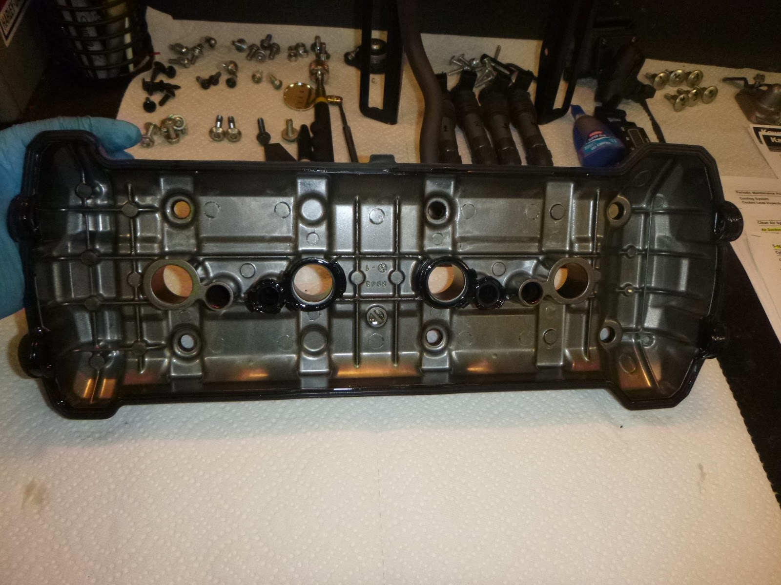
Finally, I can see the Cams!
Left side.

Right side.

There are four retainer pins that hold the four spark plug gaskets in place. These are loose and could be removed so as not to interfere when testing clearances.

The next step that precedes clearance measurement was placing the pistons in the proper position, which is Top Dead Center or TDC. This was done by turning the crankshaft gear located under the Crankshaft Sensor Cover. The photo below is the Crankshaft Sensor Cover. There are some brackets in this photo that are associated with my aftermarket Power Bronze Belly Pan.

The crankshaft gear (shown below) reflects markings for TDC of pistons #1, #4 and #2, #3. This gets a little confusing, but following the Service Manual, I only used the TDC mark for pistons #1, #4 at the completion of the compression stroke to check clearances.

In its position of TDC 1.4 in the photo above ^, the piston is at the completion of the compression stroke and valves for either piston #1 or piston #4 are closed. The other of those two pistons was placed at TDC wherein its valves are all closed by turning the crankshaft gear 360 degrees using a 17 mm socket and ratchet as shown below. So, the way this works is every full turn of the crankshaft gear alternates Piston #1 and Piston #4 as being at TDC at the end of the compression stroke.

Once the pistons are properly positioned, the table below (derived from the Service Manual) outlined the specific valves that are closed (including valves associated with pistons 2 and 3) and for which clearances could be measured. It provides that when piston #1 is at post-compression TDC, I was free to measure clearances on the exhaust valves of cylinders 1 and 2 and the intake valves of cylinders 1 and 3. Then I would rotate the camshaft gear 360 degrees placing piston #4 at post-compression TDC, at which time I was free to measure clearances on the exhaust valves of cylinders 3 and 4 and the intake valves on cylinders 2 and 4.

The next table (also derived from the Service Manual) shows the lobe position and the proper method for insertion of the feeler blade.

So, as an example, below is a clear view from the left side of the engine of an exhaust lobe (left) and an intake lobe (right) with piston #4 at TDC, which could be established from the lobe position table just above.

Now, I went back to the second table up and note that these two lobes (that are associated with cylinder 1) need to be tested with piston #1 at TDC. That was accomplished with one full turn of the crankshaft gear.

At this point, it was just a matter of using the feeler gauges to measure the clearances and writing them down as I went along. I was very careful not to leave a feeler gauge in the cam lobe! I've heard of that happening.

One thing that I considered, if I got a bad reading, I'd rotate the camshaft gear two full turns to get the piston I'm testing out of and then back to TDC and test it again. Under my overall approach, if ultimately, after discussion with my dealer, a valve or valves is determined to be out of tolerance, the procedure would be to replace the shim (shim under bucket) as shown in photo below.

Since I am not planning on making shim replacements, this is a topic not addressed in this post. However, given how tight the current exhaust tolerances are on my Versys 1000, I am taking the recommendation of my dealer to move up the clearance measurements to 10,000 miles (or 28,500). At that point I may be replacing shims. That'll be a lot more work than is reflected in this post, but that's okay. It just means that I'm keeping my motorcycle well maintained.
Wednesday, November 4, 2015
BILT Typhoon Jacket
I purchased a BILT Typhoon Jacket from Cycle Gear back in 2011 and really put it through the meat grinder. I wore it on several adventure challenges including rides in Texas (the inaugural Texas Adventure Challenge, for example), Utah and British Columbia, plus a few other places. I even did a 12,500 mile trip to Alaska and back with the BILT Typhoon.

The Typhoon Jacket has a heavy denier outer shell and a non-detachable waterproof liner. It also has a detachable thick quilted liner.

The jacket had plenty of straps to real it in tightly, the zippers always worked fine and the waterproof liner did a good job keeping the wet out.
It's pouring and 35 degrees in this photo below taken on my way up to Tok, Alaska (in July 2012) and ultimately up to Deadhorse. Yes, I had a couple layers under there, but the jacket held the rain out and kept me warm enough for the trip. I believe Typhoon came in a pant also, but I didn't have that; the pant below is a triple-layer Alpinestar bibbed Drystar in textile and boots are Alpinestar fully waterproof Adventure Boots.

Anyway, the only problem with the Typhoon Jacket was that over a couple years, virtually all the snaps on the pockets and sleeves broke (ripped right out of the material), plus it obviously looked pretty rough (although in a kewl sorta way). Big dilemma. It wasn't quite a toss out, but it was a little too rough to use regularly.
Then recently I was in Cycle Gear getting a helmet replaced and told them about the jacket and how well it did and how much I liked it. When I told them the snaps all broke, they told me to bring it in and they'd replace it under the 5 year warranty, even though it's not even in stock any more. So that's what I did! And they replaced it with a brand new jacket that I picked up today! Woohooo, right as we go into the Fall/Winter riding season I've got a fresh new jacket!
I've got to hand it to Cycle Gear. Sometimes their stuff isn't the best, but it always seems to get the job done and when it doesn't they stand behind the stuff with their guarantee.
Monday, November 2, 2015
Sugarloaf Mountain Loop
Yes, we do have an official "mountain" in Florida. Located northwest of Orlando, it's called Sugarloaf Mountain and it's the highest point of elevation on the Florida Peninsula at 312 feet!

It's a nice area and a nice ride. Weather was great. The ride through Sugarloaf isn't that long, but when you tack on my ride up and back it was a 200 mile day. There it is.

The ride also gave me a good 5+ hours in my new Seat Concepts Saddle.

It's a nice area and a nice ride. Weather was great. The ride through Sugarloaf isn't that long, but when you tack on my ride up and back it was a 200 mile day. There it is.

The ride also gave me a good 5+ hours in my new Seat Concepts Saddle.
Sunday, November 1, 2015
Fall Break
We don't have a riding season in Florida, but I've always held that it's all downhill through the Holidays after Halloween ... starting November 1 ... today. That pretty much means that the Holidays consume all the family interests and time, and significant riding is put on the back burner until next year. Short, day trips are still in order such as my ride up to Sugarloaf I have planned for tomorrow, but I'm pretty much stuck in Florida until the Spring.
 Lake Okeechobee, Florida
 Green Pond Road, Green Swamp
What these couple months are good for, however, is some serious maintenance. In particular are all those major maintenance items that take a lot of time and effort to do. At 18,293 miles, I'm sitting right on a point where I need to get a few procedures taken care of. Here is the short list that I plan to get knocked out before 20,000 miles:


Stay tuned for details on my progress on these maintenance items. Then I can work on my 2016 touring plan!


What these couple months are good for, however, is some serious maintenance. In particular are all those major maintenance items that take a lot of time and effort to do. At 18,293 miles, I'm sitting right on a point where I need to get a few procedures taken care of. Here is the short list that I plan to get knocked out before 20,000 miles:
- Brake Fluid Change (requires DOT4)
- Coolant Change (2.7 Quarts)
- Spark Plugs (CR9EIA-9, found them on eBay for $7 each!)
- Air Filter Element (No. 11013-0712)
- Valve Clearances and, if necessary, Shim Replacement (one member reported being out of spec at 20K miles)
- Steering Stem Bearing Repacking (it has ball and race bearings; can you believe that?)


Stay tuned for details on my progress on these maintenance items. Then I can work on my 2016 touring plan!

Subscribe to:
Posts (Atom)