

The 2015 Kawasaki Versys 1000 LT has an inline 4 cylinder, 1043 cc engine, where each cylinder has two intake valves and two exhaust valves. Accordingly, there are 4 valves per cylinder and 16 total valve clearances that require measurement.
The first valve clearance service interval for U.S. and Canadian models is 15,200 miles. Due to an extended trip out west, I had racked up 18,500 miles before getting to my valve clearance measurements. That's not to say that was okay. Rather, it's my understanding that the first valve clearance measurement is the most important. I just got carried away on a road trip.

I'll start with my results and then I'll go through an overview of the process with photos to get the results.
First off are the tolerances established by the manufacturer as provided in the Service Manual:
- Exhaust = 0.22 mm - 0.31 mm
- Intake = 0.15 mm - 0.24 mm
Since there are a lot of numbers involved, I prepared the template shown below on Microsoft Excel to keep track. From past experience doing this, I've learned that it's important to have a feeler gauge set with a good range of blade sizes for better precision. When using feeler gauges, you're not actually measuring the clearance; you're just sliding a piece of metal under the cam lobe. The more of those blades you have in your set that are inside the tolerance ranges (above), the more precise the measurement. My set is a Sears Craftsman 26 blade, angled feeler gauge. Of that set, a total of 9 blades were within the tolerance range.
Even with a good blade range, my approach for calculating clearance is averaging (Average) the largest blade that I could fit under the lobe (Fit) and the next size up (No Fit). There are other methods. My dealer thought this approach was okay.

Other details on my template ^ are the shim replacement sizes (determined by a table in the Service Manual) and the manufacturer's part number for shims. Please note that the 2.95 mm shim size is the the original shim presumably installed at the factory. When making shim replacement decisions the shims need to be removed and measured using a micrometer because they do wear and you really need to be sure.
For the record, I am not re-shimming the two out-of-spec valves (red measurements) because they're only a matter of a couple hundredths of a mm out of the tolerances. However, I made that decision only after talking to my dealer's service department. Consider the information in the table following the clearance measurements for illustrative purposes only.
Overall, the process involved to check the valves took between six and seven hours, excluding reassembly. I'm still waiting on the replacement valve cover gasket, jeesh!
Aside from a feeler gauge set with a good range of blades, there were no special tools needed.
There are a number of original equipment replacement parts called for as follows:
- Valve Cover Gasket (No. 11061-0914)
- Spark Plug Gaskets (No. 11061-0104)
- Valve Cover Bolt Grommets (No. 92055-0785)
- Camshaft Senor Cover Gasket (No. 92055-0199)
Also, there will not be a better time to replace the spark plugs (NGK CR9EIA-9), air filter element (No. 11013-0712) and the coolant than during this exercise to get to the valves for tolerance measurement. I'm definitely taking advantage of the opportunity.
Of course, I have a Service Manual and referred to it to do these procedures. There's a lot in there about this process that ain't in this post. In addition, I found the exploded parts diagrams on the Kawasaki Website to be very helpful. After all, pictures are worth a thousand words. The diagrams I found most helpful were the Cylinder Head Cover, Camshaft(s)/Tensioner, Cylinder Head and Valve(s).

...and a good clean work space. A high pressure air hose on a compressor came in handy to blow out the engine compartment.

The first steps involve removal of all the fairings ... and this bike has a lot of fairings! Fairing removal includes both the nose cone and the side panels. Fairing removal is covered in the Service Manual, Chapter 15-9, and I won't go over what I did in detail. It's about a 2 hour exercise. However, there is an outstanding post on the Versys 1000 Forum that I follow and has step by step fairing removal and lots of pictures. Click the link below:
Tech Tip: How to Remove Fairings on 2015 V1K, by Gharsaman.
With all the fairings removed, I then did the following:
- Loosen handle bar and turn up for more clearance to the engine compartment.
- Disconnect the negative lead on the battery.
- Perform the procedures to lift the fuel tank up on its pivot (the Service Manual calls for removal of the fuel tank).
- Remove the Air Box.
- Remove the Stick Coils.
- Cushion and cover to avoid damage.

Okay, here's where I was at when I got all those procedures done. Caped off the throttle bodies so no contamination get in there and then disconnected and removed the stick coils.

I numbered the stick coils although I'm not sure that replacement to the same cylinder is necessary. Better to be safe than sorry, though.

The next step was to remove the Air Switching Valve (Service Manual, Engine Top End 5-13, 14) and the Air Suction Valve Covers. Note that there's an electrical connector shown in the photo that was disconnected.

With the Air Switching Valve Removed, I could push the rubber cover over the top of the engine into the front area in front of the cylinder head and out of the way. Then the two Air Suction Valve Covers could be removed.


The Service Manual then calls for the Air Suction Valves to be removed. However, I couldn't get them out. They're actually reed valves and I just didn't want to put too much pressure on them and end up breaking or bending them. So I left them installed and there was no interference when I ultimately got to pulling the valve cover.

At this point, the valve cover can be unbolted and removed. There are a couple methods that I considered in getting the cover out of the frame. However, both approaches result in the valve cover being slid out on the right side of the frame.
The first method, which is the Service Manual approach, is to remove the radiator cap housing bolt, which in turn loosens the radiator housing and hoses. Then the housing/hoses can be pulled up and out of the way while the valve cover is slid underneath.

Alternatively, I unhooked the front radiator hose, unscrewed the housing bolt and then lifted the whole assembly out of the way. Not only did this make the valve cover removal easier, it also offer up some more room for working on the valves when I got to that point. See how much more room you have below compared to the photo above?

However, to go my route, the coolant needed to be drained and replaced. It's quite an easy procedure, although I made it a little messy.


Now it was clear sailing to remove the six valve cover bolts and slide the valve cover out the right side of the frame. As it relates to the six bolts, it should be noted that there is a special order for reinstalling them when I get to that. That order is provided on the both the valve cover and in the Service Manual (Cylinder Head Cover 15-18).


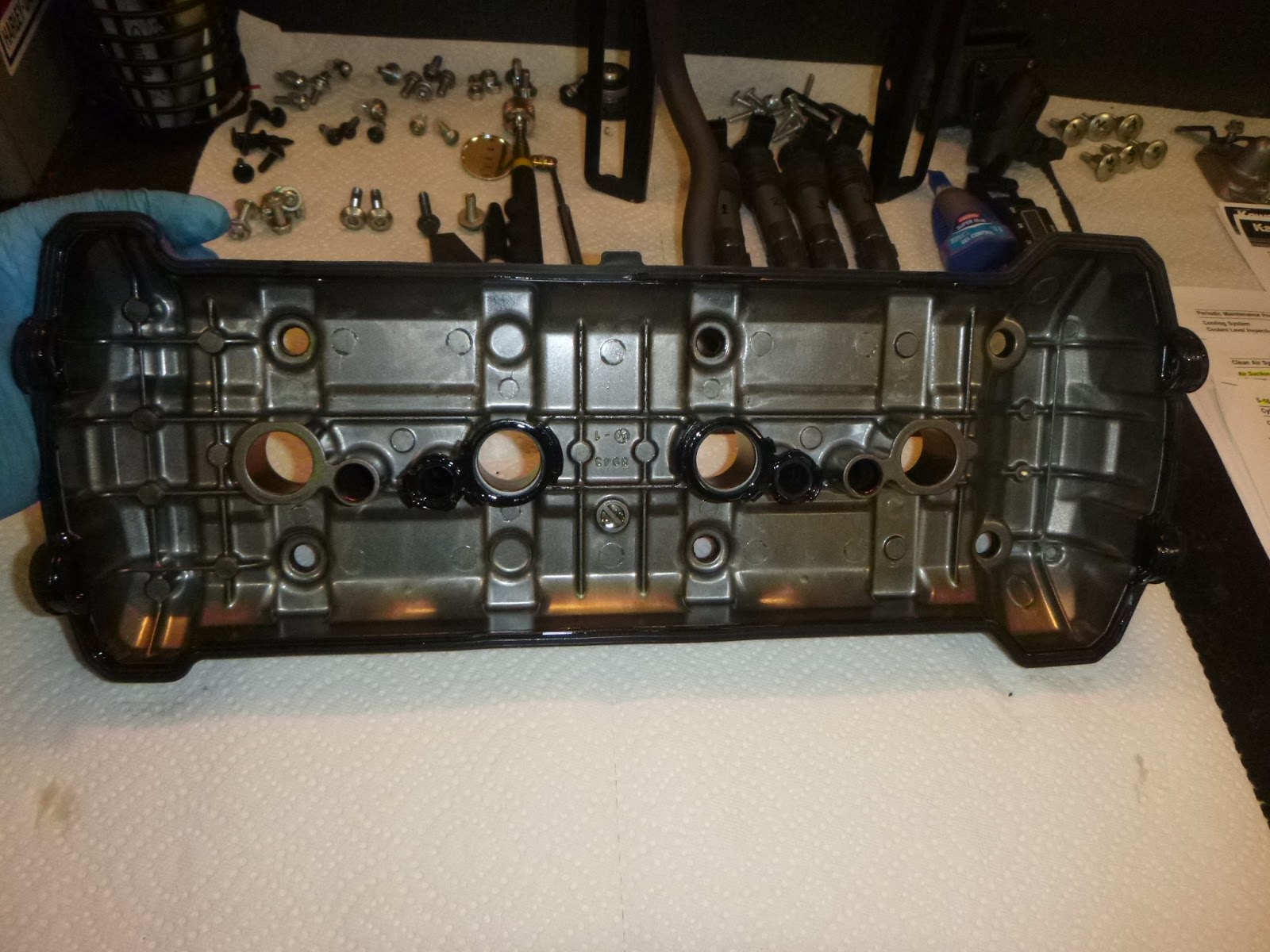
Finally, I can see the Cams!
Left side.

Right side.

There are four retainer pins that hold the four spark plug gaskets in place. These are loose and could be removed so as not to interfere when testing clearances.

The next step that precedes clearance measurement was placing the pistons in the proper position, which is Top Dead Center or TDC. This was done by turning the crankshaft gear located under the Crankshaft Sensor Cover. The photo below is the Crankshaft Sensor Cover. There are some brackets in this photo that are associated with my aftermarket Power Bronze Belly Pan.

The crankshaft gear (shown below) reflects markings for TDC of pistons #1, #4 and #2, #3. This gets a little confusing, but following the Service Manual, I only used the TDC mark for pistons #1, #4 at the completion of the compression stroke to check clearances.

In its position of TDC 1.4 in the photo above ^, the piston is at the completion of the compression stroke and valves for either piston #1 or piston #4 are closed. The other of those two pistons was placed at TDC wherein its valves are all closed by turning the crankshaft gear 360 degrees using a 17 mm socket and ratchet as shown below. So, the way this works is every full turn of the crankshaft gear alternates Piston #1 and Piston #4 as being at TDC at the end of the compression stroke.

Once the pistons are properly positioned, the table below (derived from the Service Manual) outlined the specific valves that are closed (including valves associated with pistons 2 and 3) and for which clearances could be measured. It provides that when piston #1 is at post-compression TDC, I was free to measure clearances on the exhaust valves of cylinders 1 and 2 and the intake valves of cylinders 1 and 3. Then I would rotate the camshaft gear 360 degrees placing piston #4 at post-compression TDC, at which time I was free to measure clearances on the exhaust valves of cylinders 3 and 4 and the intake valves on cylinders 2 and 4.

The next table (also derived from the Service Manual) shows the lobe position and the proper method for insertion of the feeler blade.

So, as an example, below is a clear view from the left side of the engine of an exhaust lobe (left) and an intake lobe (right) with piston #4 at TDC, which could be established from the lobe position table just above.

Now, I went back to the second table up and note that these two lobes (that are associated with cylinder 1) need to be tested with piston #1 at TDC. That was accomplished with one full turn of the crankshaft gear.

At this point, it was just a matter of using the feeler gauges to measure the clearances and writing them down as I went along. I was very careful not to leave a feeler gauge in the cam lobe! I've heard of that happening.

One thing that I considered, if I got a bad reading, I'd rotate the camshaft gear two full turns to get the piston I'm testing out of and then back to TDC and test it again. Under my overall approach, if ultimately, after discussion with my dealer, a valve or valves is determined to be out of tolerance, the procedure would be to replace the shim (shim under bucket) as shown in photo below.

Since I am not planning on making shim replacements, this is a topic not addressed in this post. However, given how tight the current exhaust tolerances are on my Versys 1000, I am taking the recommendation of my dealer to move up the clearance measurements to 10,000 miles (or 28,500). At that point I may be replacing shims. That'll be a lot more work than is reflected in this post, but that's okay. It just means that I'm keeping my motorcycle well maintained.
Nice post and thanks for sharing!
ReplyDeleteGREAT post thankyou
ReplyDeleteExcellent thanks for your help
ReplyDeleteGood job
ReplyDeleteHi hellow everyone im about to get a 2016 kawasaki versys 1000 with 14500 the owner told me that the manual says that it need the valve adjustment at 15000miles but want to know where i can take it to do it or what happens if i wait lil but more than 15000 miles the guy says it is in perfect condition but is that cost much valve adjustment
ReplyDeleteIf you can't do it yourself, the clearances should be checked and, if necessary adjusted, by a dealer or a qualified motorcycle repair shop. Adhering to the manufacture's spec maintenance intervals is advisable.
Delete